UART Guide
UART Information
High Risk Hardware Modification
UART modification requires advanced technical skills and will void your warranty. Proceed at your own risk. Incorrect connections can permanently damage your device.
What Is UART?
UART (Universal Asynchronous Receiver-Transmitter) is a hardware communication protocol that allows serial communication between devices.
It is essential for:
- Low-level debugging and recovery
- Accessing bootloader and system console
- Flashing firmware when other methods fail
- Diagnosing boot issues
Why Use UART on AW1000?
The AW1000 UART interface provides direct access to the device bootloader and system console, bypassing higher-level security.
This is useful for:
- Recovering from failed firmware updates
- Bypassing locked bootloaders
- Debugging kernel panics
- Modifying low-level configurations
UART Connection Details
- Baud Rate:
115200 - Data Bits:
8 - Parity:
None - Stop Bits:
1 - Flow Control:
None - Voltage Level:
3.3V TTL
UART Pin Layout (J6 Connector)
[1] [2] [3] [4]
 .   .   .   .
 |   |   |   |
GND RX  TX VCC(3.3V)
- Pin 1:
GND(Ground) - Pin 2:
RX(Receive - connect to TX of USB-TTL) - Pin 3:
TX(Transmit - connect to RX of USB-TTL) - Pin 4:
VCC 3.3V(do NOT connect to USB-TTL VCC)
Required Tools
- USB to TTL serial converter (3.3V compatible)
- Dupont jumper wires (female-female)
- Small Phillips screwdriver
- Plastic prying tools
- Terminal software (PuTTY, TeraTerm, etc.)
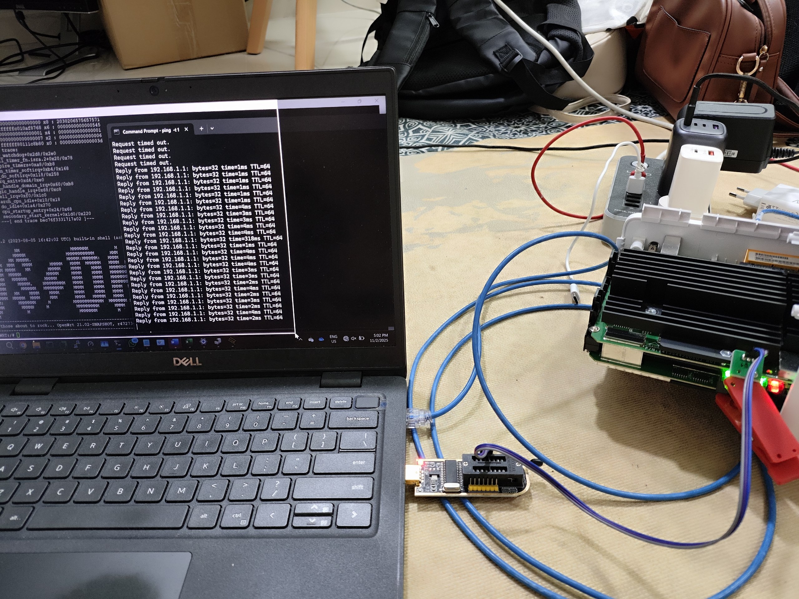
TTL USB Reference Image

Use the diagram above as a quick reference for connecting your USB-to-TTL adapter to the AW1000 UART pins (TX, RX, GND). Do NOT connect VCC from the adapter to the device.
Connection Steps
- Power off the AW1000 and remove the back cover.
- Locate the J6 UART connector near the main board.
- Connect wires:
- USB-TTL
GND-> Pin 1 (GND) - USB-TTL
RX-> Pin 3 (TX) - USB-TTL
TX-> Pin 2 (RX) - Configure terminal to
115200,8N1, no flow control. - Power on the device while monitoring serial output.
Boot Process Output
U-Boot 2012.07-g5e66bd4-dirty (Aug 15 2022 - 14:32:10)
DRAM: 512 MiB
NAND: 128 MiB
In: serial
Out: serial
Err: serial
Net: eth0, eth1
Hit any key to stop autoboot: 3
Tip: During boot, you have 3 seconds to press any key to enter U-Boot console.
Common UART Commands
| Command | Purpose |
|---|---|
reset |
Reset to factory defaults |
boot |
Boot from different partition |
setenv bootargs "console=ttyMSM0,115200n8" |
Set environment variables |
saveenv |
Save environment |
printenv |
Print environment variables |
AW1000 UART Flashing Procedure
- Turn off modem completely before starting.
- Install required software:
- UART module drivers for your PC/laptop
- TFTPD server (
tftpd.exe) - Serial terminal (
putty.exe) - Connect module to UART points on AW1000:
- Ground (UART module) -> Ground (modem)
- RX (UART module) -> TX (modem)
- TX (UART module) -> RX (modem)
- Connect LAN cable to the yellow LAN port on modem.
- Set static IP on laptop:
- IP:
192.168.1.2 - Subnet:
255.255.255.0 - Gateway:
192.168.1.1 - Open TFTPD application:
Downloads and Required Software
-
AW1000 UART files (Google Drive): Download on Google Drive
-
Open PuTTY:
- Select
Serialconnection type - Set speed to
115200 - Select COM port detected in Device Manager
- Turn on modem while rapidly tapping space bar on PC.
- Run UART commands:
1-tftpboot aw1000-mibib.bin
2-flash 0:MIBIB
3-tftpboot factory.bin
4-flash rootfs
- Wait for completion. When successful, turn off modem and power back on.
Important
Only connect GND, RX, and TX. Do NOT connect the VCC pin on the modem to your UART module.
Credits
Project by SopekSemprit (2023-2025).